
What Makes Metal-Sealed Butterfly Valves Ideal for High-Velocity Hydro Turbine Service?
Hydropower plants depend on reliable water control between the penstock and turbine. In high-velocity service, the inlet valve must withstand substantial hydraulic loads, provide dependable isolation, and operate without creating damaging pressure fluctuations. A metal-sealed Butterfly Valve can be a suitable choice when its sealing structure, body strength, actuator, and closing sequence are engineered for the actual operating conditions. Metal-to-metal sealing is particularly relevant where long-term contact with water, repeated operation, and demanding shut-off requirements make material durability an important consideration.
For turbine inlet applications, however, sealing material is only one part of the engineering decision. Flow velocity, static head, transient pressure, disc torque, and water hammer must all be evaluated together. Dafugui Pipe Valve Co., Ltd. supplies metal hard-seal butterfly valves and hydraulic control check butterfly valves, including configurations intended for hydropower turbine inlets. The distinction matters: the general metal hard-seal series is described for low-pressure pipeline media and on-off operation, while the hydraulic control check series combines a large-diameter valve with a controlled hydraulic operating system for water conveyance applications.
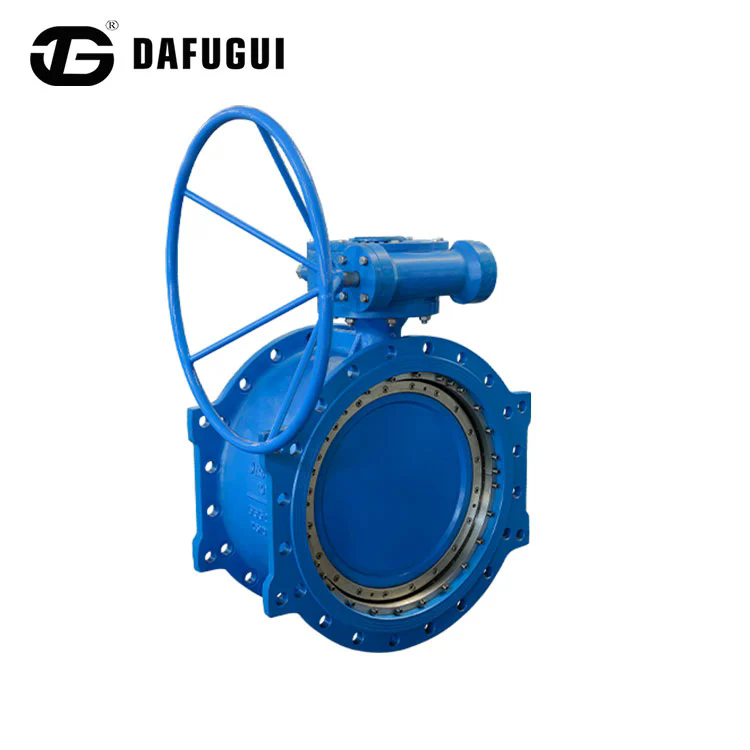
Table of Contents
1. Why Does Metal-to-Metal Sealing Matter in High-Velocity Hydro Service?
2. Which Valve Parameters Determine Suitability for a Hydro Turbine Inlet?
3. How Do Hydraulic Actuation and Controlled Closure Protect the Waterway System?
4. Conclusion: How Can Buyers Specify the Right Valve for a Hydropower Project?
Why Does Metal-to-Metal Sealing Matter in High-Velocity Hydro Service?
A turbine inlet valve operates in a demanding part of a hydropower installation. It is positioned in the waterway between the penstock and the turbine, where it may be required to isolate the unit for maintenance or respond to an emergency shutdown. Depending on the station layout, the valve can be exposed to high static head, substantial differential pressure, flow-induced torque, and transient loads associated with changes in turbine operation. The sealing arrangement must therefore remain mechanically stable while providing the required shut-off performance.
Metal-to-metal sealing uses metallic contact surfaces rather than relying entirely on an elastomeric seat. This construction can be advantageous in applications where temperature variation, mechanical loading, ageing, or repeated operation place additional demands on the sealing components. A metal sealing ring can also be designed as a replaceable component, allowing maintenance teams to inspect or renew the sealing element without treating the entire valve as a disposable assembly. The actual service life still depends on material selection, surface finish, alignment, operating differential pressure, and the quality of installation.
How Does an Eccentric Disc Reduce Sealing Contact During Operation?
In a conventional concentric butterfly valve, the disc and seat remain in relatively close contact as the valve rotates. Depending on the design and operating conditions, this can create friction along the sealing surfaces. Eccentric designs change the relationship between the shaft, disc, and seat geometry. By moving the shaft away from selected centre lines, the design can reduce rubbing during opening and closing and allow the sealing surfaces to engage mainly near the end of the closing stroke.
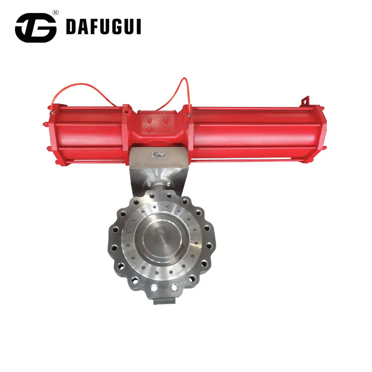
A triple eccentric arrangement uses three geometric offsets to achieve a cam-like movement between the disc and seat. As the disc approaches the closed position, the sealing surfaces engage in a controlled manner. During opening, the disc moves away from the seat, helping reduce continuous sliding contact. This is one reason triple offset metal-seated designs are commonly considered for applications that require a robust metallic sealing interface.
For a hydro turbine installation, the potential benefits include:
- Reduced rubbing at the seat: The eccentric geometry helps limit prolonged contact between the disc and sealing ring during travel.
- Metallic sealing interface: A metal-to-metal arrangement can be selected where elastomeric materials are not preferred for the specified operating conditions.
- Replaceable sealing components: A replaceable metal sealing ring can support inspection and maintenance planning.
- Compact quarter-turn operation: The disc rotates through approximately 90 degrees, providing a compact arrangement for large pipeline isolation.
- Material flexibility: Different body, disc, and sealing materials can be considered according to water quality, corrosion exposure, and mechanical loading.
These advantages do not mean that every metal-seated design is automatically suitable for every hydro turbine. A metal seal must be matched to the design pressure, maximum differential pressure, allowable leakage, flow direction, and actuator torque. Sediment, suspended solids, and debris can also damage a sealing surface if the valve is operated under unsuitable conditions. A project specification should therefore define the expected water quality and the required inspection standard.
Why Is Disc Position Important at High Flow Velocity?
The disc is located directly in the flow passage. When the valve is fully open, its geometry still affects the available flow area and local hydraulic losses. When the disc is partly open, the flow accelerates around the disc edges and can create local pressure changes, turbulence, vibration, and uneven hydraulic loading. The resulting forces can influence actuator torque and place additional stress on the shaft, bearings, body, and sealing surfaces.
In clean water service, the main concerns may include flow-induced vibration, pressure distribution, and hydraulic loss. In water containing sand or other abrasive particles, local high-velocity zones can also increase erosion. If the valve is held close to the seat while carrying substantial flow, the narrow passage can expose the sealing surfaces and adjacent body areas to concentrated flow. This is why the operating duty must be defined clearly: an isolation valve that normally remains fully open or fully closed has a different design requirement from a control valve intended for continuous throttling.
Our evaluation of a turbine inlet application should begin with the flow and pressure conditions, not simply the nominal pipe diameter. Engineers need to establish the normal operating flow, maximum flow, static head, transient pressure, expected operating frequency, and the valve positions used during startup and shutdown. These inputs help determine whether the selected eccentric structure and actuator can operate within the required mechanical and hydraulic limits.
Dafugui Pipe Valve Co., Ltd. describes its metal hard-seal design as an eccentric metal-to-metal structure with a replaceable metal sealing ring. The product information also identifies triple, four, and five eccentric configurations. These structures provide different design options, but the correct configuration must be selected against the project's pressure, temperature, material, and operating requirements rather than assuming that the most complex eccentric arrangement is always the best choice.
Which Valve Parameters Determine Suitability for a Hydro Turbine Inlet?
Valve selection for a hydropower project involves more than checking whether the nominal diameter matches the penstock. The selected valve must be compatible with the system's design head, maximum transient pressure, waterway geometry, flow velocity, and required operating sequence. The body and disc must withstand the mechanical loads, while the sealing system must provide the specified isolation performance. Actuator sizing must also consider hydraulic torque, differential pressure, operating speed, and the required fail-safe action.
The Dafugui product range includes a general metal hard-seal butterfly valve and a separate hydraulic control check butterfly valve. Both offer metal hard-seal configurations, but their published parameter ranges are not identical. The following comparison keeps the two product groups separate so that buyers can use the data correctly during preliminary selection.
| Parameter | Metal hard-seal series | Hydraulic control check series |
| Nominal diameter | Triple eccentric: DN50 to DN5000; four and five eccentric: DN50 to DN1600 | DN400 to DN5000 |
| Nominal pressure | Triple and four eccentric: PN10 to PN420; five eccentric: PN10 to PN260 | PN10 to PN40 |
| Published temperature range | Triple eccentric: -196 to +550 degrees C; four eccentric: -253 to +650 degrees C; five eccentric: -269 to +800 degrees C | -29 to +350 degrees C |
| Sealing options | Triple eccentric, four eccentric, and five eccentric metal hard seals; layered multi-level hard sealing | Double eccentric rubber soft seal; triple eccentric multi-level hard seal; triple eccentric metal hard seal |
| Connection types | Double flange, clamp, lug, and butt welded | Double flange |
| Design standards listed | ASME, API, ISO, EN, GOST, JIS, GB | ASME, API, AWWA, ISO, EN, GOST, GB |
| Actuation and operating arrangement | Configuration depends on the selected valve and actuator package | Hydraulic operating system with counterweight or accumulator-based energy storage |
| Typical application described by manufacturer | Industrial, metallurgical, and environmental protection pipelines for ventilation and flow isolation | Hydropower turbine inlets and pump outlets in water conservancy and power pumping stations |
The temperature and pressure ranges shown above are published product-family ranges. They should not be interpreted as a single valve being capable of operating at every listed pressure and temperature combination. Actual pressure-temperature ratings depend on the selected body material, trim, size, design standard, and project conditions. A final datasheet and manufacturer confirmation are necessary before procurement.
Which Materials Should Be Considered for Waterway Service?
Material selection depends on the water chemistry, sediment content, operating head, corrosion exposure, and mechanical loads. A valve installed in a clean freshwater system may require a different material combination from one exposed to abrasive silt, high dissolved mineral content, or corrosive water. The body, disc, shaft, sealing ring, fasteners, and bearing components should be reviewed as a complete assembly.
The published metal hard-seal product information identifies the following material groups:
- Carbon steel: WCB, WCC, LCC, LC1, and LC3 for body and pressure-containing component options subject to the relevant material grade and design conditions.
- Low-temperature carbon steel: LCB, LCC, LC1, and LC3 for specified low-temperature configurations.
- Chromium-molybdenum alloy steel: WC6, WC9, and C5 for applications requiring alloy steel properties.
- Martensitic stainless steel: 420, 410, 17-4PH, and CA15 for selected strength, wear, or corrosion requirements.
- Austenitic stainless steel: CF8, CF8M, CF3, CF3M, 321, 347, XM-19, and 310 for different corrosion and temperature conditions.
- Duplex stainless steel: 2205, 2507, F51, F53, and F55 for selected strength and corrosion-resistance requirements.
- Nickel-based and cobalt-based alloys: Inconel 625, Inconel 718, Monel 400, Monel K500, Nitronic 60, and Stellite grades for specialised service requirements.
These are available material families, not a universal bill of materials for every water turbine project. For example, a stainless steel grade should not be selected solely because it has a corrosion-resistant designation. Its strength, weldability, compatibility with the mating material, and suitability for the water chemistry must also be checked. Hard-facing and sealing materials should be assessed for erosion resistance and contact behaviour under the specified conditions.
What Hydraulic and Mechanical Data Must Be Confirmed?
Before approving a valve for a turbine inlet, engineering teams should establish the actual duty points. The valve may be required to open after pressure equalisation, remain fully open during generation, and close during planned shutdown or emergency isolation. Each operating stage creates a different load case. The actuator must be capable of moving the disc under the specified differential pressure, while the closing profile must meet the hydraulic transient limits of the waterway.
The following information should be included in the project datasheet:
| Engineering input | Why it is required | What the buyer should provide |
| Penstock and turbine inlet diameter | Establishes the valve size and interface geometry. | Pipe internal diameter, flange dimensions, and installation drawings. |
| Static head and design pressure | Defines the steady pressure load on the valve. | Maximum static head and design pressure at the valve location. |
| Transient pressure | Accounts for pressure rise or drop during shutdown, load rejection, and emergency closure. | Hydraulic transient study and maximum/minimum pressure envelope. |
| Flow rate and velocity | Determines hydraulic loading, flow losses, and potential vibration or erosion risks. | Normal, maximum, and minimum flow conditions. |
| Water quality | Influences corrosion, abrasion, and sealing surface protection. | Suspended solids, sediment size, water chemistry, and temperature. |
| Operating differential pressure | Influences disc torque, opening conditions, and actuator sizing. | Pressure on both sides of the closed valve and equalisation requirements. |
| Closing sequence | Controls the relationship between valve movement and water hammer. | Normal closing time, emergency closing time, and staged travel requirements. |
| Leakage requirement | Defines the required isolation performance and acceptance criteria. | Specified leakage class or project-defined seat leakage limit. |
Hydropower design guidance highlights the importance of designing the turbine inlet valve for maximum transient pressure, not only steady-state pressure. It also emphasises that the valve passage should avoid abrupt changes in velocity and that head loss should be considered when determining the valve size and flow path. These considerations are especially important in high-head installations, where an incorrect valve size or closure strategy can increase the hydraulic loads on the penstock and turbine inlet.
Our technical review should therefore distinguish between the general metal hard-seal valve data and the hydraulic control check configuration. The latter is the more directly relevant product family for turbine inlet duties because its published application includes hydropower turbine inlets and its operating system is designed around controlled opening and closing. Dafugui Pipe Valve Co., Ltd. provides both product categories, allowing the project team to assess the required valve structure and operating arrangement against the actual waterway design.
How Do Hydraulic Actuation and Controlled Closure Protect the Waterway System?
In a hydropower plant, the valve does not operate in isolation. It works as part of a water conveyance system that includes the reservoir or intake, headrace, penstock, turbine, wicket gates, and associated protection equipment. When the flow changes rapidly, pressure waves travel through the waterway. These hydraulic transients can create pressure surges, low-pressure zones, vibration, and additional structural loads. The way the inlet valve moves during an operating event can therefore be as important as its ability to seal when fully closed.
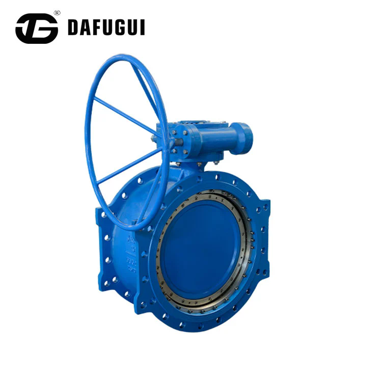
A hydraulic control check butterfly valve combines a butterfly disc with a hydraulic operating mechanism. In Dafugui's published design, the closing force can be provided by the potential energy of a counterweight or by compressed energy stored in an accumulator. The hydraulic power unit supplies pressure to operate the cylinder and associated mechanism. This arrangement can provide controlled opening, staged closing, and a defined response when the power supply or hydraulic system is interrupted, depending on the selected configuration.
How Does a Counterweight and Hydraulic System Work?
In a counterweight arrangement, the weight provides stored mechanical energy for valve closure. During opening, the hydraulic pump supplies pressurised oil to the cylinder. The piston acts through a lever mechanism to lift the counterweight and rotate the valve disc toward the open position. When the closing sequence is initiated, the counterweight supplies the force required to move the valve toward its closed position.
This operating principle is useful where a project requires a defined closing response that does not rely exclusively on continuous electrical power. The hydraulic system controls the movement, while the counterweight provides the closing energy. The design still requires proper sizing of the cylinder, lever, counterweight, and hydraulic circuit. The available closing torque must be checked against the maximum hydraulic torque acting on the disc under the specified flow and pressure conditions.
The manufacturer's published operating description includes several operating sequences:
- Opening: The oil pump supplies pressure to the cylinder, lifting the counterweight and moving the disc toward the open position.
- Hydraulic pressure holding: The system maintains pressure after opening, with the accumulator providing stored hydraulic energy where configured.
- Automatic pressure replenishment: The oil pump restores accumulator pressure when it reaches the specified low-pressure threshold.
- Normal or emergency closure: The counterweight drives the disc toward the closed position according to the preset hydraulic control sequence.
- Manual emergency operation: The manufacturer describes manual pump operation as an option for operation when normal power is unavailable.
The published accumulator pressure range for the hydraulic control check valve is 20 to 32 MPa. This is the hydraulic accumulator pressure, not the waterway's nominal pressure rating. Keeping these two values separate is essential when preparing the project datasheet. The hydraulic pressure operates the actuator system; the valve body pressure rating applies to the water flowing through the pipeline.
Why Is Two-Stage Closing Important for Water Hammer Control?
Water hammer occurs when a flowing water column experiences a rapid change in velocity. The resulting pressure wave can travel along the penstock and reflect at changes in geometry, reservoirs, valves, and other hydraulic boundaries. In a turbine installation, rapid wicket-gate movement, emergency shutdown, load rejection, or uncontrolled valve closure can contribute to transient pressure changes.
A staged closing profile is one way to manage the relationship between valve travel and flow reduction. Dafugui describes a two-stage closing sequence in which the valve first closes rapidly to cut off approximately 70 percent of the water flow, followed by a slower closing stage for the remaining 30 percent. The purpose is to reduce the severity of the final flow interruption and help limit water hammer.
The percentages describe the manufacturer's stated operating sequence. They should not be copied directly into every project control setting without hydraulic analysis. The relationship between disc angle and actual flow is nonlinear, and the percentage of valve travel is not necessarily equal to the percentage of flow reduction. The appropriate fast-closing point, slow-closing point, and total closing time must be determined through the plant's hydraulic transient study.
For example, a long penstock with a high flow velocity may respond differently from a shorter waterway with a different wave speed and surge-control arrangement. A closing sequence that is acceptable in one station may create excessive pressure rise or low-pressure conditions in another. Engineers should therefore check the maximum and minimum transient pressures at critical locations, including the valve, penstock, and turbine inlet.
When Should a Metal-Sealed Valve Be Used for Isolation Rather Than Throttling?
This distinction is particularly important in high-velocity water service. A turbine inlet valve is generally designed to isolate the turbine, not to replace the turbine governor or wicket gates as the normal flow-regulating device. During normal generation, the inlet valve is commonly held fully open while the turbine governing system adjusts the water admission. The inlet valve closes for isolation, maintenance, or defined protection sequences.
Dafugui's general metal hard-seal product page specifies that the valve should be used in fully open or fully closed positions and should not be used for flow regulation. The manufacturer warns that throttling can cause erosion of the sealing surface and accelerate wear. This is a significant selection point for a high-velocity application. A metal seal may offer a durable isolation interface, but it does not make a standard on-off valve suitable for continuous throttling at high flow velocity.
For the turbine inlet application, the engineering team should confirm:
- The valve's normal operating position during power generation.
- Whether the valve is required to close against full flow or only after the turbine wicket gates have reduced the flow.
- The maximum differential pressure at the start of opening.
- Whether a bypass line is required for pressure equalisation before opening.
- The allowable closing time and the required staged closure profile.
- The maximum hydraulic torque acting on the disc during the full operating sequence.
- The expected water quality and the possibility of sediment-related erosion.
- The inspection and testing requirements for the metal sealing surfaces.
FIST commissioning guidance for hydroelectric facilities also stresses the need to verify smooth and uniform valve movement, measure opening and closing times, and adjust the hydraulic circuit to match the plant's hydraulic transient design. These checks help confirm that the installed operating sequence corresponds to the engineering calculations rather than relying only on a nominal actuator setting.
What Should Be Checked During Installation and Commissioning?
Even a correctly specified valve can underperform if it is installed out of alignment or commissioned without checking the complete actuator sequence. Large-diameter valves are heavy mechanical assemblies, and the pipeline supports, flange alignment, lifting arrangements, and access for maintenance all need to be considered before installation.
A practical commissioning review should cover the following areas:
- Dimensional verification: Confirm the face-to-face dimension, flange drilling, nominal diameter, pressure class, and installation orientation against the approved drawings.
- Flow direction and disc clearance: Check the manufacturer's installation instructions and confirm that the disc can move through its full travel without interference from adjacent pipework.
- Mechanical inspection: Inspect the shaft, bearings, sealing ring, fasteners, and actuator linkage for visible damage or abnormal movement.
- Hydraulic system checks: Verify oil condition, accumulator pressure, pump operation, cylinder movement, and hydraulic leakage.
- Position indication: Confirm that open, closed, and intermediate position signals correspond to the actual disc position.
- Operating-time measurement: Record opening and closing times and compare them with the project requirements.
- Emergency sequence testing: Verify the specified emergency response and confirm that the closing profile is consistent with the approved transient analysis.
- Maintenance readiness: Confirm access to the actuator, hydraulic unit, inspection points, and any mechanical locking arrangements.
Our commissioning plan should include documented test results rather than relying only on a successful no-load movement test. Where the design requires closure under flow, the test procedure must be approved by the project engineer and coordinated with plant safety requirements. A valve's no-flow operating time may not represent its actual closing behaviour under hydraulic load.
Dafugui Pipe Valve Co., Ltd. identifies the hydraulic control check series for turbine inlet and pump outlet applications. For a project involving high-velocity water, the final configuration should be reviewed against the system's hydraulic calculations, water quality, transient limits, and maintenance strategy. The manufacturer's product range provides the starting point for this review, while the project datasheet and approved drawings establish the final requirements.
Conclusion: How Can Buyers Specify the Right Valve for a Hydropower Project?
Metal-to-metal sealing, eccentric disc geometry, and replaceable sealing components can make a metal-sealed Butterfly Valve a practical option for demanding isolation duties. In hydropower service, however, reliable performance depends on more than the sealing interface. The valve must be sized for the penstock, rated for the design and transient pressure, matched to the water quality, and operated through a closing sequence that protects the waterway against damaging hydraulic transients. Continuous throttling at high velocity should not be assumed suitable for a standard metal hard-seal isolation valve.
Dafugui Pipe Valve Co., Ltd. offers metal hard-seal configurations as well as a hydraulic control check series designed for hydropower turbine inlet applications. If you are specifying a valve for a turbine inlet, penstock, or pumping station, contact our team with the design pressure, flow rate, waterway drawings, operating sequence, and material requirements. We can review the application and help identify a suitable valve configuration and hydraulic operating arrangement for your project.
Frequently Asked Questions
Why are metal-sealed butterfly valves considered for high-velocity hydro turbine applications?
Metal-sealed designs use metallic contact surfaces that can be selected for demanding isolation conditions, while eccentric disc geometry helps reduce rubbing between the disc and seat during operation. These features can support durable shut-off service when the materials, pressure rating, sealing arrangement, and actuator are correctly specified. For turbine inlet duty, the valve must also be designed for the waterway's hydraulic loads and transient pressure conditions. A metal seal alone does not guarantee suitability for every high-velocity or high-head application.
Can a metal hard-seal butterfly valve be used to regulate turbine water flow continuously?
Not necessarily. Dafugui's general metal hard-seal product information specifies fully open or fully closed operation and advises against using that product for flow regulation because throttling can erode the sealing surface and accelerate wear. In a typical hydropower arrangement, turbine flow is regulated by the governing system and wicket gates, while the turbine inlet valve provides isolation. Any alternative operating duty should be confirmed through the manufacturer's technical review and project-specific hydraulic calculations.
How does a hydraulic control check butterfly valve help reduce water hammer in a hydropower plant?
A hydraulic control check butterfly valve can use a preset opening and staged closing sequence to manage how quickly water flow is reduced. In Dafugui's published design, a counterweight supplies closing energy, while the hydraulic system controls valve movement. The stated two-stage closing arrangement first reduces approximately 70 percent of the water flow and then closes the remaining portion more slowly. The actual closing points and total time must be established through hydraulic transient analysis because water hammer depends on flow velocity, penstock characteristics, valve position, and system layout.
Related News
- Why Is Quick Shut-Off Capability of Butterfly Valves Essential for Turbine Protection?
- What Role Do Butterfly Valves Play in Protecting Pumps from Surge Pressure Events?
- Why Do Desalination Plant High Salinity S32760 Threaded Pipe Flanges Excel in SWRO Brine and Chemical Lines?
- How Does a Butterfly Valve Control Water Flow in Municipal Supply Systems?
- What Role Do Butterfly Valves Play in Hydropower Plant Penstock Flow Regulation?
- What Is a Rubber Disc Check Valve and How Does It Ensure Reliable Backflow Prevention?
Leave me a message
News Recommendations